Circuit Diagram Of Metal Detector Using 555 Timer : Derivatives provide two (556) or four (558) timing circuits in one package.
Circuit Diagram Of Metal Detector Using 555 Timer : Derivatives provide two (556) or four (558) timing circuits in one package.. 555 timer bassed metal detector circuit with explanation electronic circuits schematics. As you can see in the schematic circuit , this metal detector electronic project requires few external electronic parts. The output of the 555 timer remains high while the pulses applied to its input occur in the correct intervals of time. As you can see in the schematic circuit , this electronic project. When metal contact is reached ,each led starts glowing.
Simple Metal Detector Circuit Diagram Using 555 Timer Ic from circuitdigest.com When the tank is full buzzer starts. When metal contact is reached ,each led starts glowing. When a magnet is brought close to the 10mh choke, the output frequency changes. This circuit detects metal and also magnets. The circuit will detect a long period pulse between a train of pulses. Monostable multivibrator is characterized by giving high. A circuit that detects metal and also magnets. As you can see in the schematic circuit , this metal detector circuit project requires few external electronic parts.
A circuit that detects metal and also magnets.
These series of pulses allow you to continuously blink an led, for example. This metal detector circuit project is designed using a simple 555 timer integrated circuit. You can watch the following video or read the written tutorial below. This circuit detects metal and also magnets. If you still need a detailed understanding of the 555 timer. 555 timer bassed metal detector circuit with explanation electronic circuits schematics. The circuit will detect a long period pulse between a train of pulses. If a pulse fall behind, or it is absent. This circuit detects metal and also magnets. Metal detector circuit is frequently found at airports, theaters, and various other public places. This article covers every basic aspect of 555 timer ic. Missing pulse detector using 555 timer ic. The figure shows the circuit diagram of metal detector.
This metal detector circuit project is designed using a simple 555 timer integrated circuit. Water level alarm using 555 timer. I even built a wireless tachometer, using a second 555 to receive and condition the what is a circuit of a metal detector without the. Metal detectors can be created easily using a coil which is the main part of the device. This circuit detects metal and magnets.
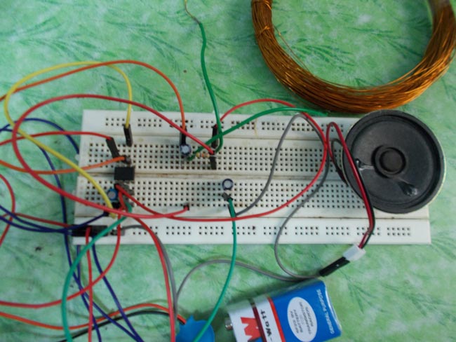
Here in this metal detector circuit we are using a timer ic 555 and inductor to detect metals and alert the user by means of an alarm from simple buzzer.
Click on icon for program. Metal detectors are used for the safety of people to detect anyone carrying a metal (arms etc). It is built around 230v ac primary to 9v, 300ma secondary transformer x1, bridge rectifier db107 (br1), 6v voltage regulator 7806 (ic1), timer ne555 (ic2) and a few other. The 555 ic is wired as a mono stable multivibrator. This missing pulse detector circuit can detect the absence or delay of a expected pulse, which should be received at predefined intervals.
Results Page 4 About Metal Searching Circuits At Next Gr from www.next.gr Electronic circuits that use the ic 555 timer, a simple metal detector electronic project can be designed using a simple 555 timer circuit. The metal detectors are the specialized ne555 timer gadgets that detect the presence of the metals when the metals enters in the range of metal detector circuits. the ne555 timer metal detectors does not only have the application i the field of security but they are also used in a variety of situations. Print the diagram in the centre of a sheet of paper create a circuit using the ics pin locations. The 555 timer ic is an integrated circuit (chip) used in a variety of timer, delay, pulse generation, and oscillator applications. The following diagrams show some unusual circuits for the lm555 timer. Missing pulse detector using 555 timer ic. I even built a wireless tachometer, using a second 555 to receive and condition the what is a circuit of a metal detector without the. #circuitguru in this video i explaind metal detector circuit diagram from ic 555!!!
They are used for the safety of people to detect anyone the above circuit shows a schematic diagram of the metal detector.
I want to build some project about metal detector using integrated circuit 555 timer. When a magnet is close the choke 10mh, output frequency changes. These circuits were developed to provide certain functions that are not typically. Circuit diagram of the motion detector. The following diagrams show some unusual circuits for the lm555 timer. The 555 timer is an integrated circuit, it is extremely versatile and can be used to build lots of different circuits. Metal detectors can be created easily using a coil which is the main part of the device. This metal detector circuit project is designed using a simple 555 timer integrated circuit. The circuit will detect a long period pulse between a train of pulses. This circuit detects metal and magnets. This bistable configuration does not use any rc timing. This missing pulse detector circuit can detect the absence or delay of a expected pulse, which should be received at predefined intervals. I already made a schematic in proteus 8 application.
Related : Circuit Diagram Of Metal Detector Using 555 Timer : Derivatives provide two (556) or four (558) timing circuits in one package..